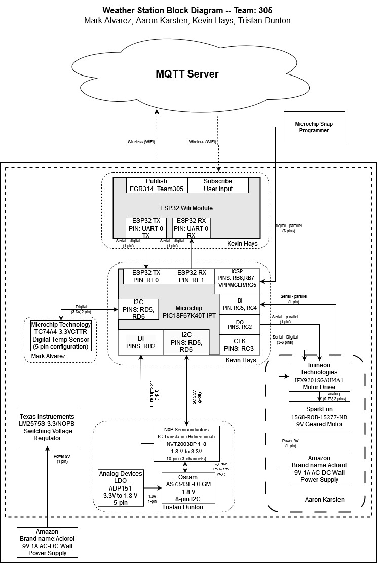
7.0 Final Block Diagram
7.1 Block Diagram

7.2 Block Diagram Overview
The team has divided the project into several subsystems, each responsible for a specific task to achieve the overall project requirements. The ESP32 is responsible for communication between the microcontroller and the internet. The PIC19(L)F67K40 is the microcontroller that manages the overall system logic, receives input from the sensors, and sends commands to the motor controller. The TC74A4 is a temperature serial sensor responsible for measuring the temperature, while the AS7343L-DLGM is a light serial sensor that measures light intensity. A ADP151 LDO regulator and a level translator have been added to the light sensor subsystem in order to give the light sensor the appropriate voltage (1.8V) and shift the logic to 3.3V. The motor controller is a serial actuator responsible for controlling the motor’s speed and direction.
All the major components used in the project are surface mount and operate at a system logic-level voltage of 3.3V. To meet the project requirements along with the user needs, the system uses at least two serial sensors and one serial actuator, using SPI and I2C for communication. Implementing the features of the product defined by user needs was accomplished by reducing the complexity of the hardware design as much as possible - without compromising the capabilities of the overall system. The system also uses UART for communicating with the ESP32. Finally, to achieve board-to-web duplex communication over WiFi, the ESP32 is responsible for communicating with the internet and exchanging data between the board and the web interface. Together, all these subsystems are designed to work in tandem to ensure the project requirements are met, user needs are addressed, and the system functions as intended.