5.0 Final Selected Design
5.1 Current Ideation
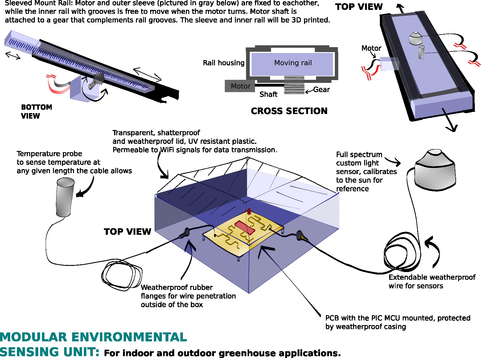
The final design features a custom 3D printed rail mounting system. The inner piece of the assembly will have a temperature and light sensor mounted to it. This piece slides freely within the outer sleeve. The outer sleeve is meant to hold the moving pieces and will be fixed to the motor. When the motor turns the shaft and gear - the grooved inner piece will move, while the motor and outer sleeve remain fixed to each other.
The second iteration of the design did not vary greatly from the final design. Having two PCBs - one for the MCU/power and the other for the sensors - was successfully implemented. Surface mount LEDs were added to the MCU PCB in order to verify that power was being delivered to the appropriate components. As a group, Team 305 made the decision to purchase a weatherproof housing instead of 3D printing a custom housing. The moisture proof flanges on the exterior of the housing were not purchased and did not become part of the final design. Ultimately 3D printing the housing would have been a better approach to improve the wire management of the entire assembly.
